|
|

Build Your Online Product Catalogs?
| Product Name: |
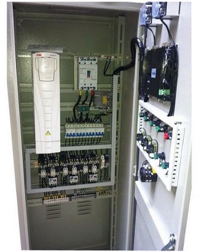
micro plc for PLC control panel in sewage treatment plant
|
| Supply Ability: |
1000 units |
| Related proudcts |
micro plc, |
| Specifications |
various models available micro plc |
| Price Term: |
FOB,CNF,CIF |
| Port of loading: |
Qingdao |
| Minimum Order |
1unit |
| Unit Price: |
500-5000USD |
|
micro plc for PLC control panel in sewage treatment plant
How micro plc works:
When the programmable logic controller is put into operation, its working process is generally divided into three stages, namely, input sampling, user program execution and output refresh three stages.
The completion of the three phases is called a scan cycle. The CPU of the programmable logic controller repeats the above three phases at a certain scanning speed during the whole operation. In this case,
1, the micro plc input sampling stage
During the input sampling phase, the programmable logic controller reads all input states and data sequentially in scan mode and stores them in the corresponding cells in the I / O map area.
After the input sample is finished, it is transferred to the user program execution and output refresh phase.
In both phases, the state and data of the corresponding unit in the I / O map area do not change, even if the input state and data are changed.
Therefore, if the input is a pulse signal, the width of the pulse signal must be greater than one scan period, in order to ensure that in any case, the input can be read.
2, the micro plc user program execution stage
During the execution of the user program, the programmable logic controller always scans the user program (ladder diagram) in order from top to bottom.
In each ladder scan, they always scan the ladder on the left side of the control circuit composed of contacts, and the first left to right, first on the lower order of the control by the contact line control logic , & Lt;
Then according to the result of logic operation, refresh the logic coil in the system RAM storage area corresponding to the state;
Or refresh the output coil in the I / O mapping area corresponding to the state;
Or to ***ermine whether or not to execute the special function instruction specified by the ladder diagram.
That is, during the execution of the user program, only the state and data of the input point in the I / O map area do not change, and the other output p |
| Company: |
Qingdao Sico Electronics Co., Ltd.
|
| Contact: |
Ms. Yaping Li |
| Address: |
Room 2004£¬ Block B Huarun Building£¬N |
| Postcode: |
266000 |
| Tel: |
8653283025965 |
| Fax: |
8653283028251 |
| E-mail: |

|
|
|
|